


When you have successfully completed this section, you will have mastered the following:
Installing wiring is more complex than ever before. With more lights and other devices being added, just finding a secure route can be difficult. One of the main sources of problems in lighting systems is the environment in which the vehicle operates. This chapter will help you to appreciate why this is true, and what you can do to protect your lighting system against harsh environmental factors.
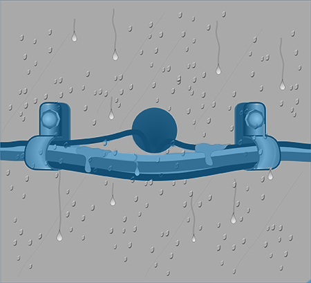
The wiring harness on a truck is constantly exposed to rain, spray, salt, snow and ice.
There are some important issues to be aware of during both the installation and repair of wiring and lighting. Some of the most important things to keep in mind are:
Moisture
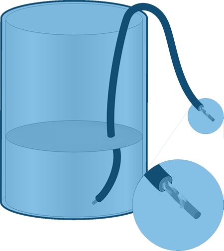
Salt Creep
When one end of an insulated wire is suspended in a flask of salt water, capillary action will cause the salt water to “creep” along the full length of the wire causing salt crystals to form at the other end of the wire.

A sudden change in temperature can create a change in pressure of as much as 4 psi between the inside and outside of a sealed wiring system. That’s enough to draw moisture into the system through any breaks in the seal.
When moving through rain showers, there are few places where a wiring system escapes getting wet. The most typical problem from moisture is that it allows electrical current to bypass the circuitry and find its own ground. Commonly called "shorting," this prevents lights or other devices from functioning. When a circuit fails to operate because current was diverted due to water penetration, the circuit has "shorted out." Moisture combines with road salt, washing compounds and other ingredients to attack the vehicle and its components. It can "wick" or travel along the strands of wire and wind up many feet from the point where it entered the system.
Water can enter the system through ineffective wire seals, unprotected splices, unsealed crimps and connectors, non-mating seals, just to name a few of the vulnerable spots. Moisture can enter virtually any opening such as cuts or cracks in the insulation and though devices that are connected to a circuit. It can enter even through sealed wiring if driven by wind and the movement of the vehicle. It can compromise otherwise tightly sealed connections if driven by a high-pressure spray. Vibration can aid in the migration of water through seals by causing them to loosen up enough for water to penetrate. Even the difference in air pressure between the outside and the inside of the wiring system can cause water to enter. So what would cause a difference in air pressure between the inside and outside of wire? Believe it or not, this can come from a sudden change in temperature. It's been shown that as much as four pounds per square inch difference can result from rapid temperature changes from inside to outside. That fast cooling is enough to cause so-called "sealed" connections to draw in water.

Splices should be protected with adhesive-lined heat-shrink tubing.
There are a number of techniques to minimize problems connected with water. Most have to do with maintaining and protecting the seals at connecting points. That's why it's important to use sealed connectors wherever possible. When making repairs, don't replace a sealed system with unsealed components. Make certain that connector seals are in place and undamaged. Inspect them carefully for cuts, tears and punctures.
All wiring connections must be sealed against moisture. For example, seal areas at splices and crimps should use adhesive lined shrink tubing. Protect all connections from high-pressure spray. The force of the spray can defeat even the best seals. If the connections can't be moved out of the effects of high-pressure cleaning, be certain that they're protected using coverings such as boots, moldings, back shells, convoluted tubing, plastic loom or other sturdy, carefully installed coverings.
In addition, any unused connector should have a cap to seal out water. Wherever possible, avoid positioning wires and connectors in high splash areas. Ensure that all coverings are in place and the wiring is securely fastened. This will prevent loose wire from hitting the vehicle structure and protect against damage that could allow moisture to penetrate the system.
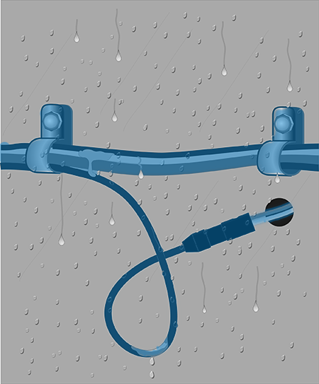
Add drip loops to direct water away from connections.
Avoid sharp bends in cable as it exits a sealed connector. A severe bend could put sufficient strain on the seals that they open up and allow moisture into the connector. Where practical, add drip loops to direct water away from connections. Never use the probe from a tester to establish contact with a wire's conductor by penetrating the insulation.
Corrosion
The ingredients for corrosion are moisture and salt or similar material. It seldom occurs in dry, sealed wiring systems. The rate of corrosion's progress depends primarily upon the type of salt present, the amount of contaminant and moisture present and the susceptibility of the metal parts to corrosion. The rate may be faster under certain conditions. Galvanic reactions can speed up the corrosion process dramatically. A galvanic reaction is generated by contact between two dissimilar metals such as when a grounding ring terminal is attached to a frame member. There are other causes for corrosion, as well. Battery acid will corrode most metals used in wiring systems. So will acid rain, though not as quickly.

Galvanic Action
You can demonstrate galvanic action by creating a galvanic battery: a stack of four pennies and four metal washers with squares of paper towel soaked with salt water between each layer. A voltmeter will detect electricity flowing from the top penny to the bottom washer. This galvanic current dramatically speeds up corrosion.
Corrosion produces a variety of bad effects. It can cause open circuits when a wire or other component is completely eaten away. It may cause an intermittent fault or short circuit, and very often result in increased resistance.
Recognizing corrosion is relatively easy. Copper is the most common material used as a conductor. Copper corrosion is a green or white powder-like substance. To help defend copper from corrosion, it's plated with a variety of metals such as tin, gold, nickel and silver. Mounting clips and fasteners are typically iron-based materials. They can be "passivated," a process for treating metal to reduce its reactivity. They may also be plated with zinc galvanizing.
To help avoid problems from corrosion, avoid situations where metal parts may be exposed to a wet or salt spray environment. Repair or replace covers, boots, or other protective devices. Consider re-routing wiring that's subject to spray, splash or battery acid. Metal parts used in wiring projects should be passivated, plated or otherwise protected from corrosion attacks.
Dielectric coatings also play an important role in sealing out both moisture and corrosive materials. Proper application of this material to sealed connections fills any voids leaving no room for moisture and other contaminants.
Consistent use will add another layer of protection and help to prevent electrical system breakdowns.
Vibration
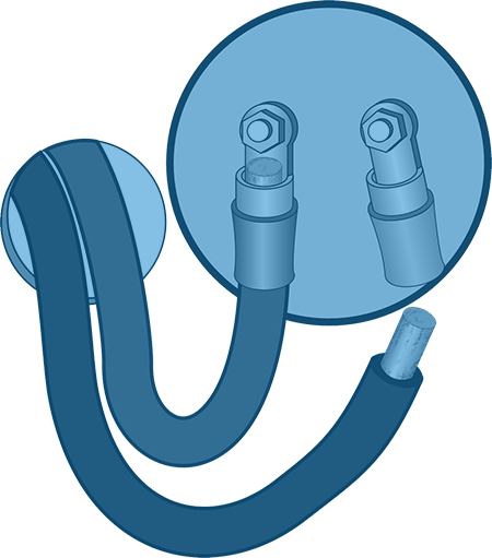
Vibration can cause connections to come apart and fail.
The two main effects of vibration are abrasion of mating surfaces and simple failure of connections or splices to remain joined. If vibration levels are minimal, normal contact forces are enough to prevent movement of mating surfaces. Wear is minimal and few connections or splices will fail. However, if vibration levels are high, mating surfaces tend to move. In that case, terminals wear very quickly. Connection failures will be frequent, causing intermittent connections, high resistance or open circuits.
"Fretting" is a condition directly related to vibration. It's a common wear process that occurs when vibration causes terminal to terminal movement. The abrasion results in the formation of wear particles, which remain in the contact area. Those particles then oxidize, causing the electrical resistance to increase. Eventually, the connection will fail. Initially, the oxide layer builds up and interferes with the electrical conduction resulting in intermittent failure. As time passes, the failures increase until the condition is permanent.
The difficulty with failures from fretting is that after an initial failure, more vibration can move the contact points back into contact temporarily. Then, as time goes by, more corrosion builds up disrupting contact again. Cycles like these can occur until the corrosion permanently creates an open circuit.
Changes in temperature can also cause fretting corrosion. Differences in the expansion and contraction rates of metals can cause small amounts of terminal-to-terminal movement that creates fretting corrosion.
There are some basic steps to help minimize vibration problems. For instance, make certain that all wires and connectors are secured appropriately. Always secure the wiring as it exits the connector. Cushioned clamps are an ideal means of mounting on high vibration locations. Where appropriate, add strain relief. Using dielectric lubricant helps prolong the life of terminal plating and delay the beginning of fretting.
Abrasion
Vibration and road shock both cause wearing away of contact surfaces. Abrasion also occurs when wires are allowed to touch wear points such as frame members and other vehicle parts. Once the insulation is worn away, bare conductors may contact a ground source and create a grounded circuit. This can also lead to corrosion, raising the resistance in the circuit. Or it could cause wear to the point of fracture resulting in an open circuit.
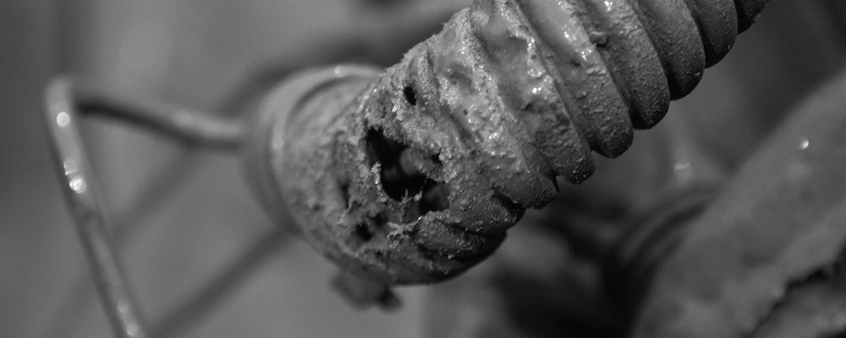
Worn coverings such as loom, convoluted tubing or spiral wrap should be replaced if they are no longer providing sufficient protection for the wires inside. Make certain that the replacement is the same size and the same material or better. Also, make certain that the covering is secured correctly. That's especially true in cases where there is the possibility of contact with moving parts such as lift gates, wheels or other equipment.
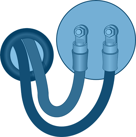
Use grommets where wires pass through and around metal parts.
Using the proper routing and coverings will help avoid wear areas and abrasion damage. Properly securing wires will also restrict unwanted movement. Keeping them in the proper location will help assure that wear is minimized or eliminated. There are other approaches to avoiding abrasion, too.
It's important to ensure that wires aren't exposed to sharp edges. Use grommets where they pass through and around metal parts. Check the insulation for signs of abrasion and replace wire if wear is detected. Always replace wire with the equivalent of the original or better. If the original wire isn't available, use a larger wire size as a replacement. For the same length of run and the same current, resistance will be greater in a smaller conductor.
Dust, Sand & Grit
Accumulation of abrasive materials on wiring and lighting devices can not only be an annoyance, it can lead to damage, especially when combined with vibration. If gritty materials enter connections, it can accelerate the wear on contact points causing interruption of the circuit and failure of the devices. Sand and grit can also attract and hold moisture, creating conditions conducive to corrosion. In some cases, sand and grit may work their way inside protective coverings and abrade the insulation of wires running through it if there is relative motion between the covering and the wire.
One of the ways of reducing sand and grit buildup is to eliminate abrasive materials in the areas where wiring is present. Another way is to seal openings on protective coverings to keep gritty materials from entering. In addition, if there are unmated connectors in the system, they may accumulate grit. They should be cleaned, dried and lubricated with a dielectric coating prior to connection to avoid abrasion problems.
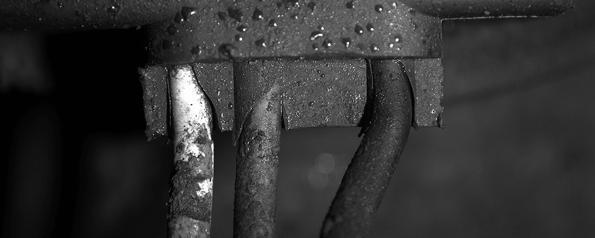
In some cases, sand and grit may work their way inside protective coverings and abrade the insulation of wires.
Impact
Wiring must be protected from the impact of rocks, gravel and other road debris. A major impact can cause enough damage to require extensive repairs. Smaller, more frequent impacts over time may deliver equally extensive damage. Damage from impacts can do damage although the wires are contained in a loom or other covering.
During inspection, always check for damage from impacts and replace any wiring or devices that appear to be damaged. Make certain that the replacement parts are equivalent to or better than the original.
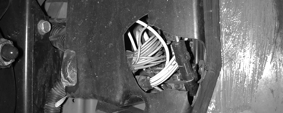
A rock thrown from a tire smashed this protective case exposing the wires and connections inside to the elements.
Chemical Exposure
The materials used in the construction of a vehicle's lighting and wiring system are resistant for short-term exposure to most chemicals. But continuous exposure to many of the common chemicals found in and around trucks can cause plastics to swell, crack, soften or otherwise become degraded. Diesel fuel and hot engine oil are the main culprits.
To minimize the effects of chemicals, inspect the wiring for signs of degradation or damage. If it is occurring in an area that is generally free of contamination check for leaky hoses, gaskets or fittings and repair if damaged or leaking.
The best way to avoid damage from chemicals is to avoid them. Don't run wiring in areas where the chance for continuous exposure is likely, such as under fuel lines and filters.
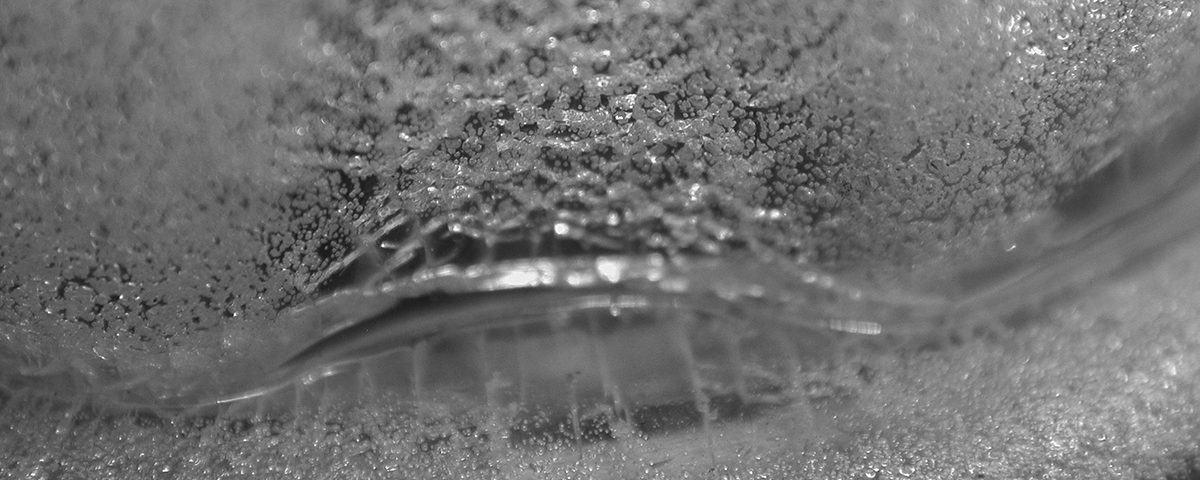
This close-up of the plastic lens on a marker lamp shows the effects of chemical damage.
Temperature Extremes
Vehicle applications require wiring components that have a wide range of temperature capabilities. For example, chassis wiring range should be from -40ºC to +80ºC. For high temperature operation, such as the engine compartment, the top of the range should be +125ºC. In those environments, especially near engine and exhaust locations, it's necessary to use high temperature wires, heat shields or reflective coverings. Without those precautions, the wiring may melt, crack, char or even burn. Some materials, if exposed to high temperatures for a prolonged time become brittle. Where wiring might be exposed to high temperatures, try to protect it against flexing and impacts.
There are several steps to take when temperature extremes exist. Inspect the system and replace any broken, cracked, distorted or seriously discolored components.
Re-route any wiring that's near a source of high heat. In situations where the routing must remain and the temperature exceeds 125ºC, use materials that are suited to the environment including high temperature insulation and heat shield material.
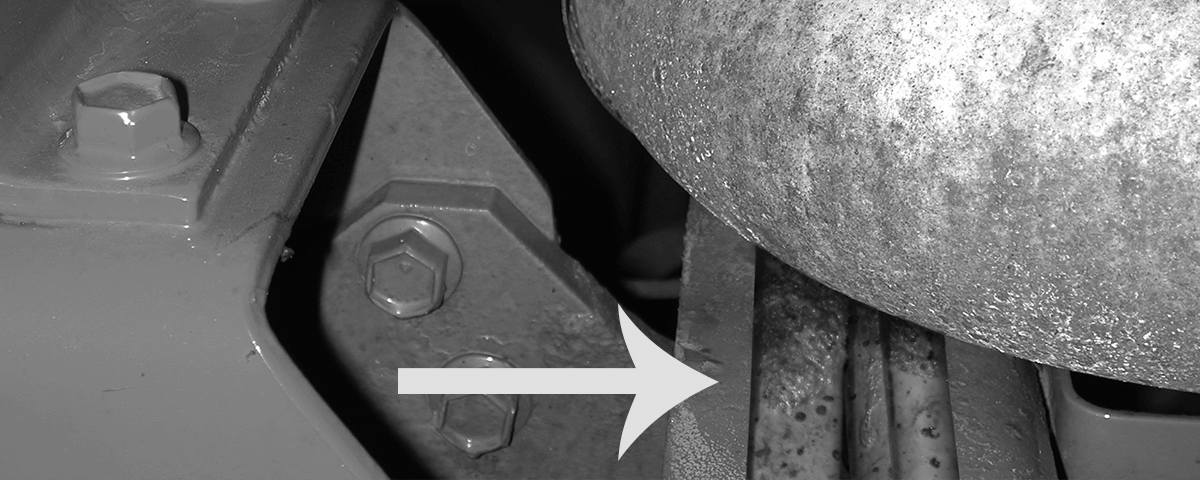
Wires routed past a hot exhaust pipe will be exposed to scorching hot temperatures that could cause damage.
Choosing Wiring Material
The most important factor in choosing wire, after selecting the gauge and choosing between solid core or multi-strand, is the temperature of the operating environment. Typically, 85º C (185° F) rated material may be used anywhere
other than the engine compartment. 120º C (248° F) rated materials can be used anywhere including high heat areas. Wire insulation, tubing and connectors have different temperature ratings that should be considered carefully when making your selection. The accompanying chart shows the continuous operating temperature ratings for many common materials.
TEMPERATURE CHART |
|||
Cable Size |
Maximum Current Carrying Capacity (For 12 Volts at Listed Temperatures) |
||
120° F |
125° F |
150° F |
|
20 Gauge |
15 Amps |
13 Amps |
9 Amps |
18 Gauge |
18 Amps |
15 Amps |
11 Amps |
16 Gauge |
22 Amps |
19 Amps |
14 Amps |
14 Gauge |
27 Amps |
23 Amps |
17 Amps |
12 Gauge |
40 Amps |
32 Amps |
24 Amps |
10 Gauge |
50 Amps |
42 Amps |
31 Amps |
Continuous Use Temperatures of Common Materials and Typical Applications |
|||||||
Typical Continuous Use Temperature (ºC/°F) |
Conductor Insulation |
Tape |
Tubing |
Connectors |
Rubber Seals |
Ties, Clips, etc. |
|
Polyethylene |
85 (185) |
|
X |
X |
|
|
X |
PVC |
85 (185) |
X |
X |
X |
X |
|
|
Hi Temp PVC |
105 (220) |
X |
X |
X |
|
|
|
Polyamide* |
120 (250) |
|
|
X |
X |
|
X |
Polypropylene* |
120 (250) |
|
|
X |
|
|
X |
X-link Polyolefin |
130 (260) |
X |
|
X |
|
|
|
Polyester (PBT)* |
165 (330) |
|
|
X |
X |
|
|
FEP |
200 (390) |
X |
|
X |
|
|
X |
TFE |
230 (500) |
X |
|
X |
|
|
X |
Silicone |
230 (500) |
|
|
|
|
X |
|
TPE* |
85 (185) - 125 (260) |
X |
|
|
|
X |
|
*Note that there are a variety of materials having these descriptions and physical properties can vary significantly. |
|||||||
Tensile Loads
Wiring should not be considered an appropriate load-bearing component. It’s easy to exceed the designed load limit by inadvertently installing wires under tension or snagging a section of wire on one of the moving parts. Using a wire bundle as a handhold or step can destroy the integrity of the conductor and connections. So can the weight of accumulated ice, snow, mud and other materials.
Too much stress on a wire may cause conductors to break, crimps to give way, and connections to pullout resulting in a system failure. Another problem arises when wires are pulled sharply to one side immediately after leaving a connector and are secured that way under tension. The stress may cause the connector’s seal to open on one side allowing moisture and contaminants to enter ultimately resulting in failure of the circuit.
To protect the integrity of the wiring, avoid tight bends in wires and bundles, especially near connector seals.Consider adding strain relief in areas subject to stress.
Never put stress on any wiring and connections. Support wires and bundles of wire approximately every 12 to 18 inches so that they are adequately supported and less likely to become snagged or pulled. Whenever possible, re-route wiring to avoid ice, snow and mud buildup.
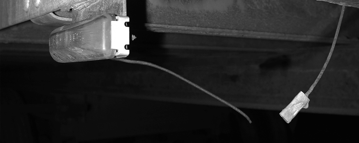
Too much stress on a wire may cause conductors to break, crimps to give way, and connections to pullout resulting in failure.
Flexing
If wiring is installed where it will be subject to repeated flexing such as around doors, hatches and moving equipment, it is subject to special stress and wear. Copper strands will fatigue with repeated flexing. Tight radius bends add to the stress. Flexing increases the possibility of pinching and snagging. The extra length required in the lengthened position and positioning of the excess wire in the shortened position also present hazards.
Some basic steps if taken will help avoid problems where wires must be subject to repeated flexing. Avoid tight radius turns. Make sure that the wire is not snagged or stressed at its maximum extension. Also, make certain that the wire moves smoothly through its flexing cycle and doesn’t rub or scrape adjacent components. When replacing wires in this situation, if special cables were used originally, be certain that the same or equivalent product is used as a replacement.

If wiring is installed where it will be subject to repeated flexing such as around doors, hatches and moving equipment, it is subject to special stress and wear.
Use the self assessment below to gauge your understanding of this section. Place your answer in the box and then check your answer by clicking on the "show answer" link.
Or, you can skip the assessment.
Instructions:
Read the question.
Place your answer in the box.
Example:
True or False:
You should read the questions and then type your answer into the box.
show answer
True!
Begin:
1. True or False: The most common effect of moisture on vehicle wiring and lighting is current diverted from it’s designated ground.
show answer
True
2. True or False: “Wicking” means migration of moisture along trailer frame members.
show answer
False
3. Sealed connections are impervious to:
show answer
d) None of the above
4. The best way to seal a connection against moisture is to use ______.
show answer
A sealed system
5. Protecting connections from high-pressure spray and road splash is easier using:
show answer
d) All of the above
6. True or False: As long as a connector is not in use, it can be left open if kept isolated using electrical tape.
show answer
False
7. Drip loops refer to:
show answer
b) A loop left in a length of wire that allows gravity to direct water away from electrical connections
8. True or False: Rapid temperature changes can cause sealed systems to draw in water.
show answer
True
9. Corrosion is commonly caused by:
show answer
c) Moisture and salt
10. True or False: Battery acid corrodes most metals found in a wiring system.
show answer
True
11. True or False: Corrosion shows up as a dark green oily substance.
show answer
False
12. Corrosion causes :
show answer
d) All of the above
13. Avoid corrosion build up by always:
show answer
d) All of the above
14. True or False: Contact between two dissimilar metals can cause a galvanic reaction leading to corrosion.
show answer
True
15. True or False: Dielectric coating reverses the action of moisture and salt.
show answer
False
16. _________, or terminal to terminal movement, leaves wear particles which can oxidize and cause greater resistance and eventually connection failure.
show answer
b) Fretting
17. True or False: With certain types of vibration-caused corrosion, an oxidized layer can cause intermittent failure.
show answer
True
18. Among the ways of minimizing vibration’s effects are:
show answer
d) All of the above
19. True or False: Abrasion can be minimized by properly securing wires, keeping them away from sharp components and using loom, convoluted tubing and other protective devices.
show answer
True
20. True or False: Sand and grit aren’t serious problems for electrical systems because, unlike corrosion, they seldom react with moisture.
show answer
False
21. True or False: Impact damage is always apparent to visual inspection.
show answer
False
22. True or False: Typically, exposure to chemicals will not harm wiring system components if limited to a short time.
show answer
True
23. True or False: Diesel fuel is not considered a chemical.
show answer
False
24. The best way to avoid the effects of chemicals on wiring systems is to :
show answer
c) Route wiring away from the source of exposure
25. True or False: The normal service temperature range for vehicle electrical components is -40ºC to +80°C with the top range at +125ºC for under hood environments.
show answer
True
26. True or False: Wire left exposed to elevated temperatures will not burn even though it may melt and crack.
show answer
False
27. Where elevated temperatures have caused damage, repairs should include inspecting the system and:
show answer
d) All of the above
28. True or False: Trailer wiring should never be used as a step or to support a load.
show answer
True
29. Wire pulled sharply to one side after leaving a connector may:
show answer
a) Cause the connector’s seal to open
30. Which of the following doesn’t help to avoid stress on wires:
show answer
d) Replace with heavier wire
31. True or False: Repeatedly flexing copper strands will strengthen them.
show answer
False